tl;dr If you are only interested in how I made my case (haha) you can jump to the next section Required parts
About four months ago I got a uGame10 for my birthday. I had seen a presentation on the device at FOSDEM a couple of days before and was immediately hooked, so I decided to put a wish out to my friends. Thanks again guys! :)
When I finally unboxed the chip I was surprised how tiny it was. Seeing a device this small, featuring a well-known Nintendo-like set of buttons, I was reminded of the small toy alarm clocks Nintendo used to make under their brand of Nintendo Mini Classics. I had a lot of fun with those mini arcade machines as a child and still admire the addictive simplicity with which those games were made. And now I held a template for such a machine in my hands, and could develop my very own pocket game machine. How exciting!
It turned on fine when I connected it to a computer and, after a firmware update, it ran all two example programs available on the web just fine. However, having a mobile device connected to a wall outlet or a bulky power bank all the time kind of defeats the point. Consequently, uGame was always designed to run off battery power. uGame’s inventor, Radomir Dopieralski, recommends to solder a specific Nokia phone battery from the 2000s directly to the pads on the device and then hot-glue it to the back of the board (see uGame manual).
If this sounds dangerous to you: It is. Soldering irons, or worse soldering guns, get very hot, and the Lithium, which is what the old battery is made of, tends to take heat as an invitation to react with everything in its proximity. Also, the contact pads and their insulation were built to a price point, and are very thin and brittle. Soldering on them is certainly not easy, and it is easy to damage or destroy the insulation, which could have all kinds of unintended consequences. But then again, Radomir goes to great lengths explaining that the device is a prototype for experienced hobbyists and not a childrens’ toy.
In addition to the risky way of fixing the battery that I did not want to follow, I faced the problem that I did not have the specific Nokia battery that was recommended in the manual. Hence, none of the case designs available online for 3D printing would have worked for me (e.g. by Jovan Maric or davedarko). I could have bought a used battery online, but you never know what state you will receive them in. I had another Nokia battery from the era handy which I tried, but I had no luck attaching wires to the battery’s pads either.
However, I was able to try if the board worked with a battery at all, and it did. I had soldered wires to the uGame, pushed the other end to the battery, and the screen was flashing on nice and bright as it did on a wire lead. Naturally, the uGame went off again when I let go, but after that short experiment I was confident that there was a way to make this work, albeit probably not with this exact battery.
I am a trained computer engineer and I have no idea of materials or 3D printing. Even if I asked my friends for help and designed a sophisticated case for “my” Nokia battery, including spring contacts to hold it in place firmly, a small PCB to extract the leads, and a snap-in plastic housing for the uGame, the case would only fit the one Nokia battery that I own. If the battery broke down it would be completely useless. Also, I work an unrelated full-time job, and this is not my only hardware project, so time is limited to some degree. Thinking along those lines, I found I best try something I have some experience with, and came up with a custom “sandwich” case design.
Required parts
a uGame10 prototype board
two through-hole printed circuit boards
The boards should feature individual soldering points to avoid short circuits when attaching the battery. Mounting holes for the cable ties (see below) come in handy, too.
a 3.7 volts Lithium battery (e.g. Sony US18650V3) and a matching holder
some wire, ideally two colours
I prefer solid wire, some prefer stranded wire, your choice basically.
about four zip ties to attach the two boards together
I would recommend having more handy, as those fiddly beasts tend to get lost easly. Sometimes you will also need to cut them when you tied the wrong things together, unless you are one of those Houdinis who can disassemble zip ties without breaking them.
Assembly
First, mount the battery holder to one of the boards. Put it on the side of the board that does not have soldering points on it, so that you will later be able to solder its connectors to the board. You may need to punch or drill small holes in the board to be able to fasten the battery holder properly. Make sure the holder does not shake or wobble when you are done: Lithium batteries are quite heavy and require solid fastening.
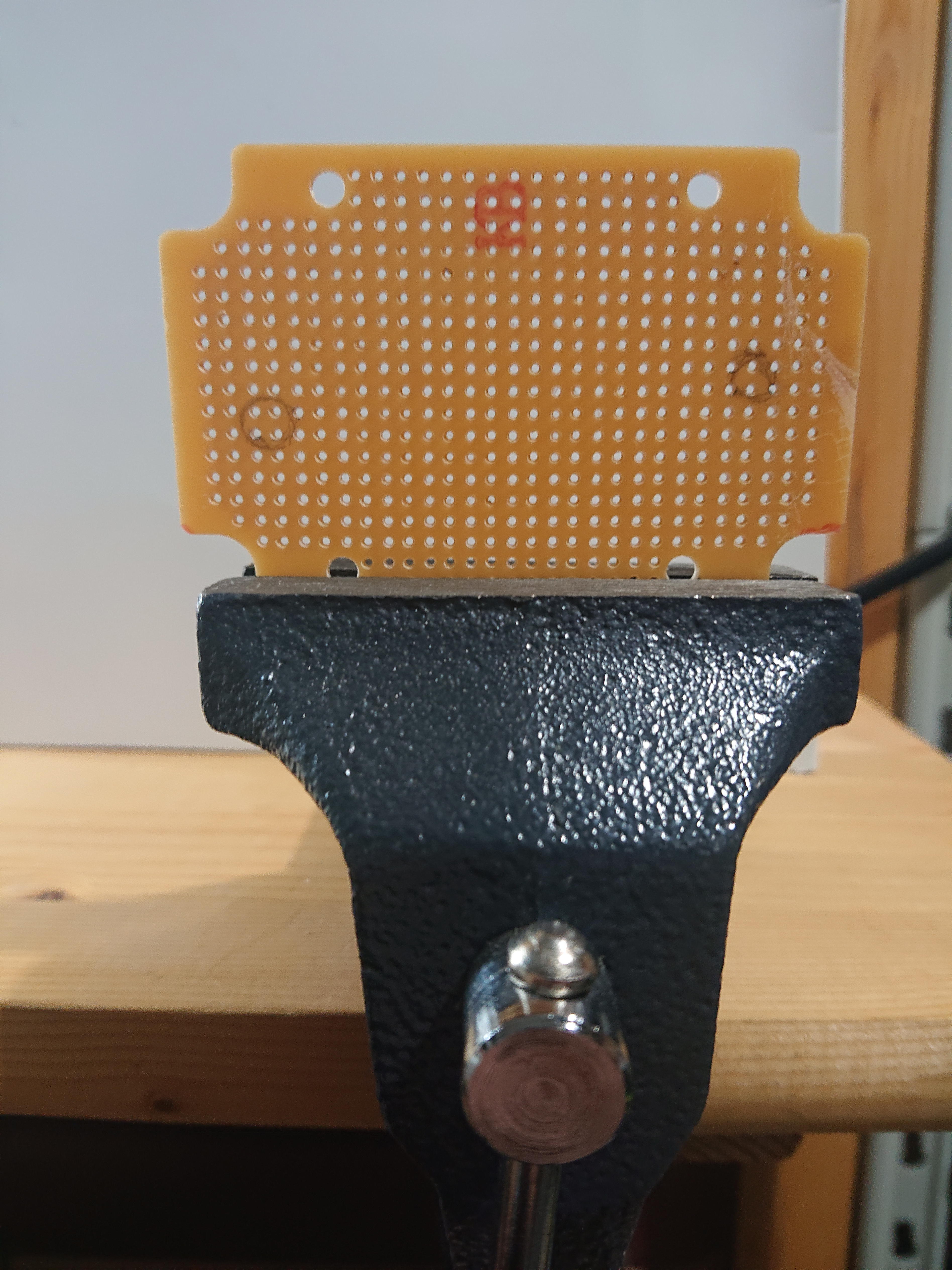
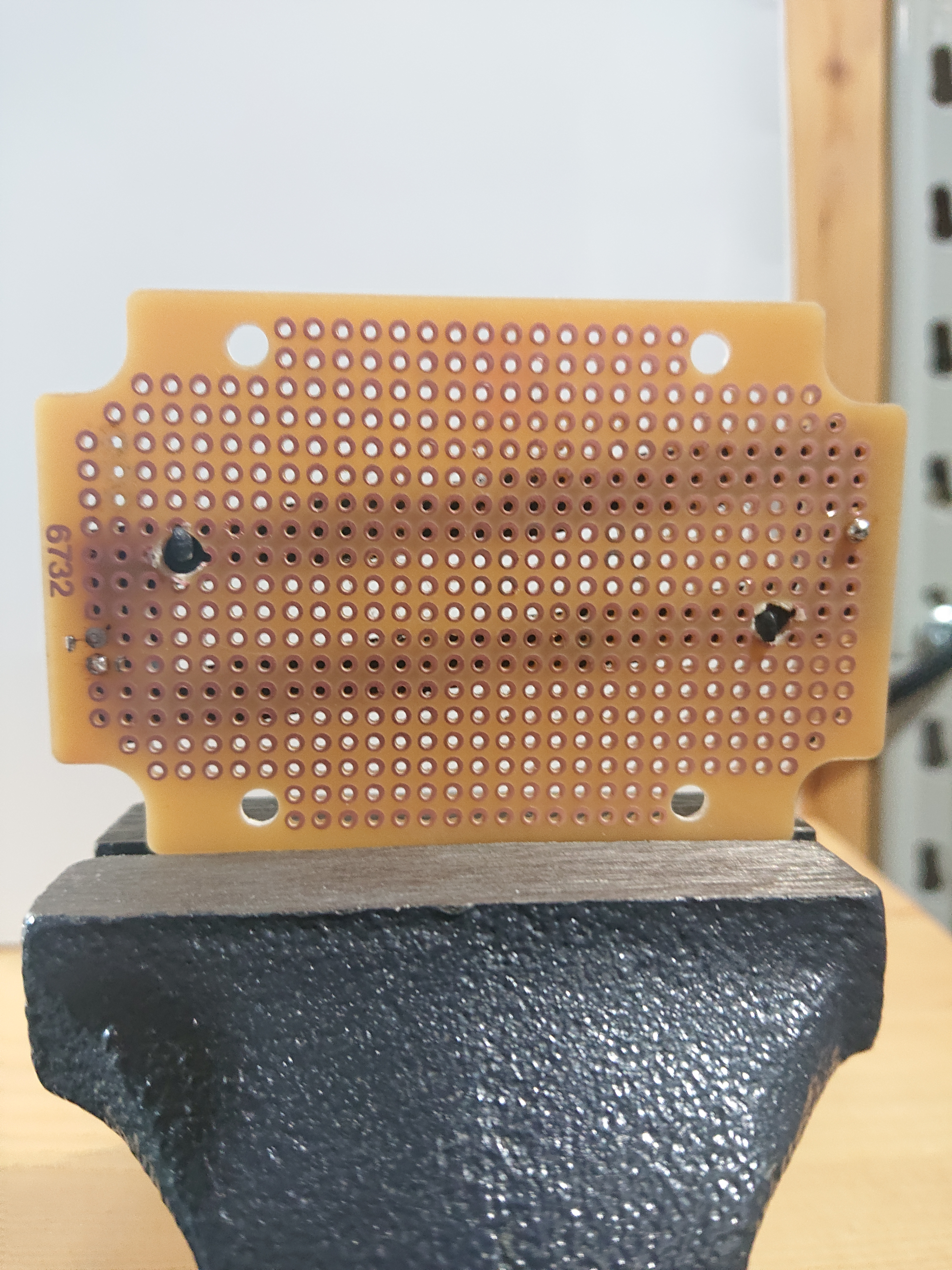
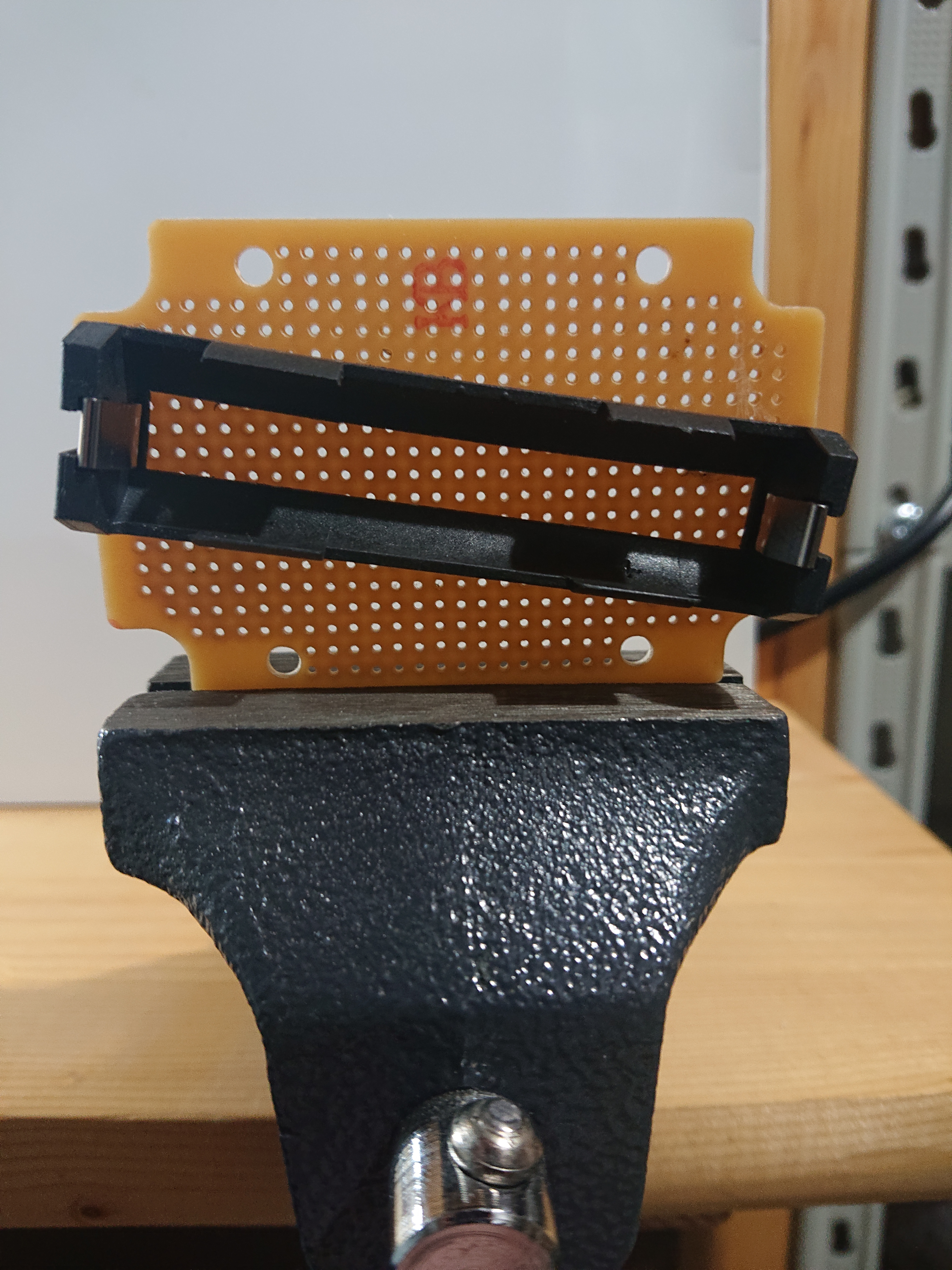
Now solder the battery holder contacts to the circuit board, and attach some wire to the solder joints. I recommend red wire for the battery’s positive end and white for the negative one. Always mind the correct polarity: If polarity is reversed when connecting the battery to the board you may destroy both the battery and the uGame!
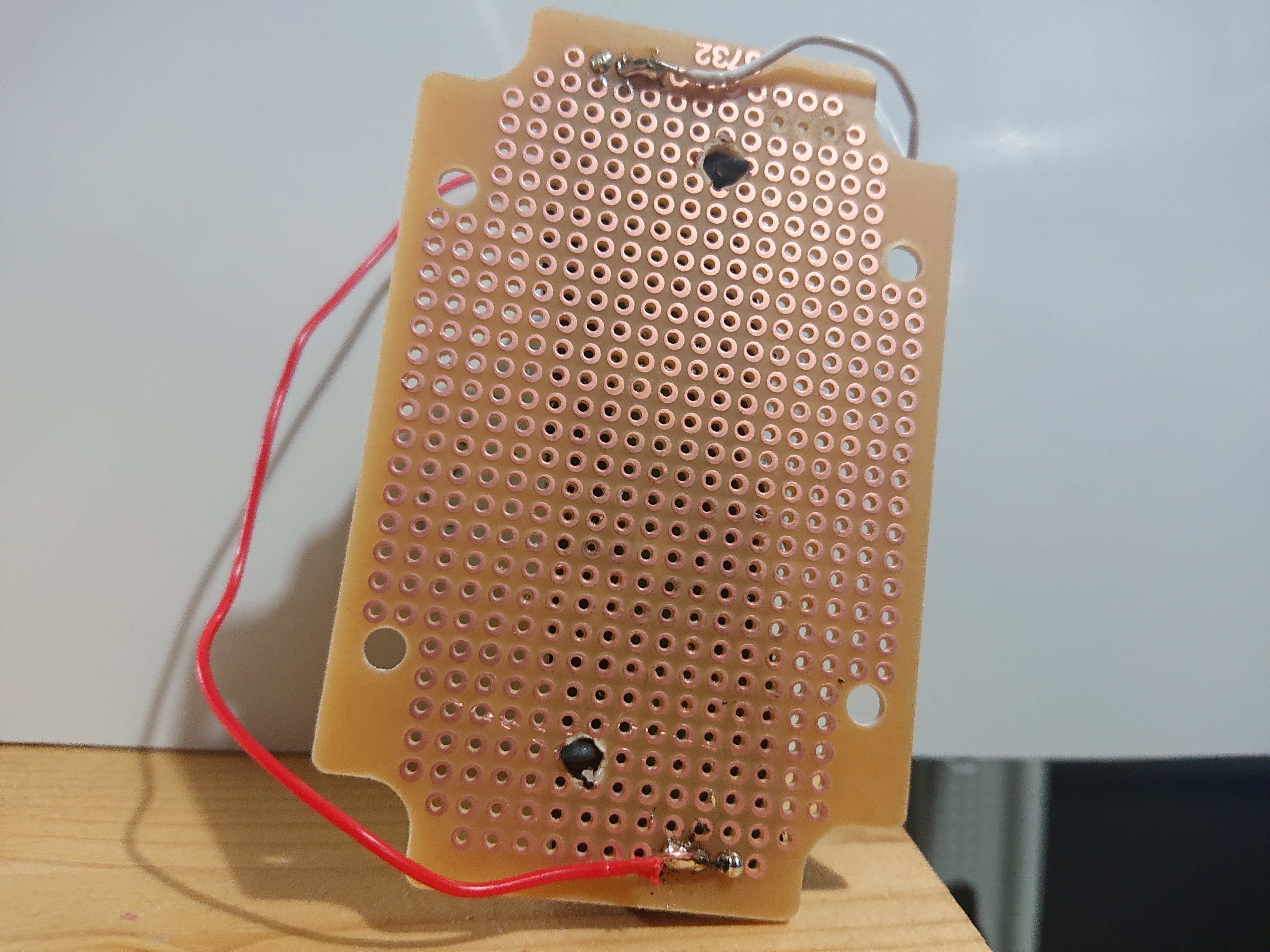
Now, solder the other ends of the wires to the back of your uGame board, matching the polarity of the battery, and attach the screen to the front of the uGame as described in the uGame manual. If you insert the battery now, you should already be able to turn on the uGame using the small up/down switch on the side. Again, mind the polarity when inserting the battery into the finished circuit! After turning on the uGame, the whole setup should look somewhat like the picture below.
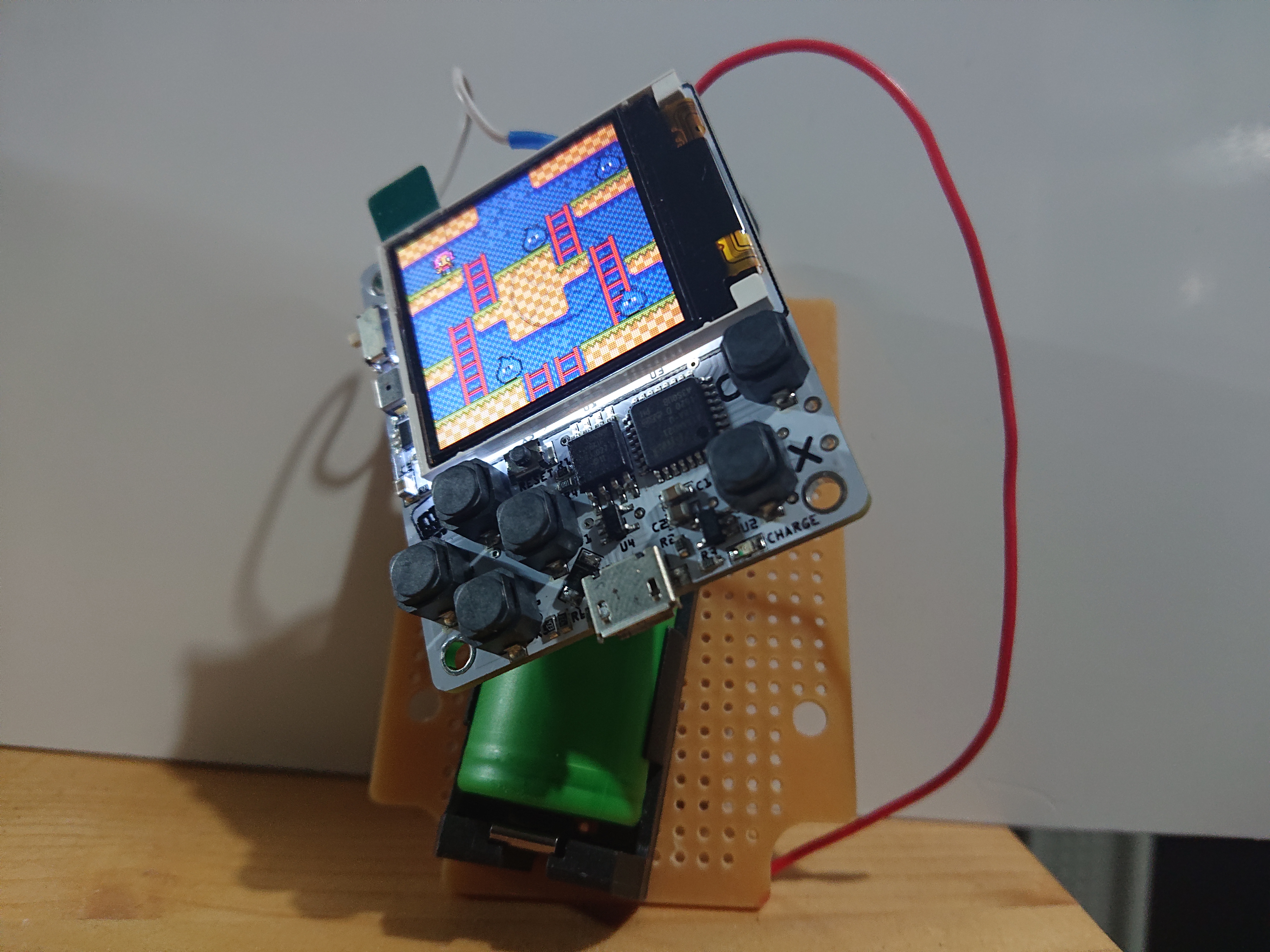
For the remaining pictures, I turned the uGame off again, because the bright light from the screen can be really disturbing when fiddling with those tiny components, but do not worry, it was working all the time.
Now you will need the other circuit board and the zip ties.
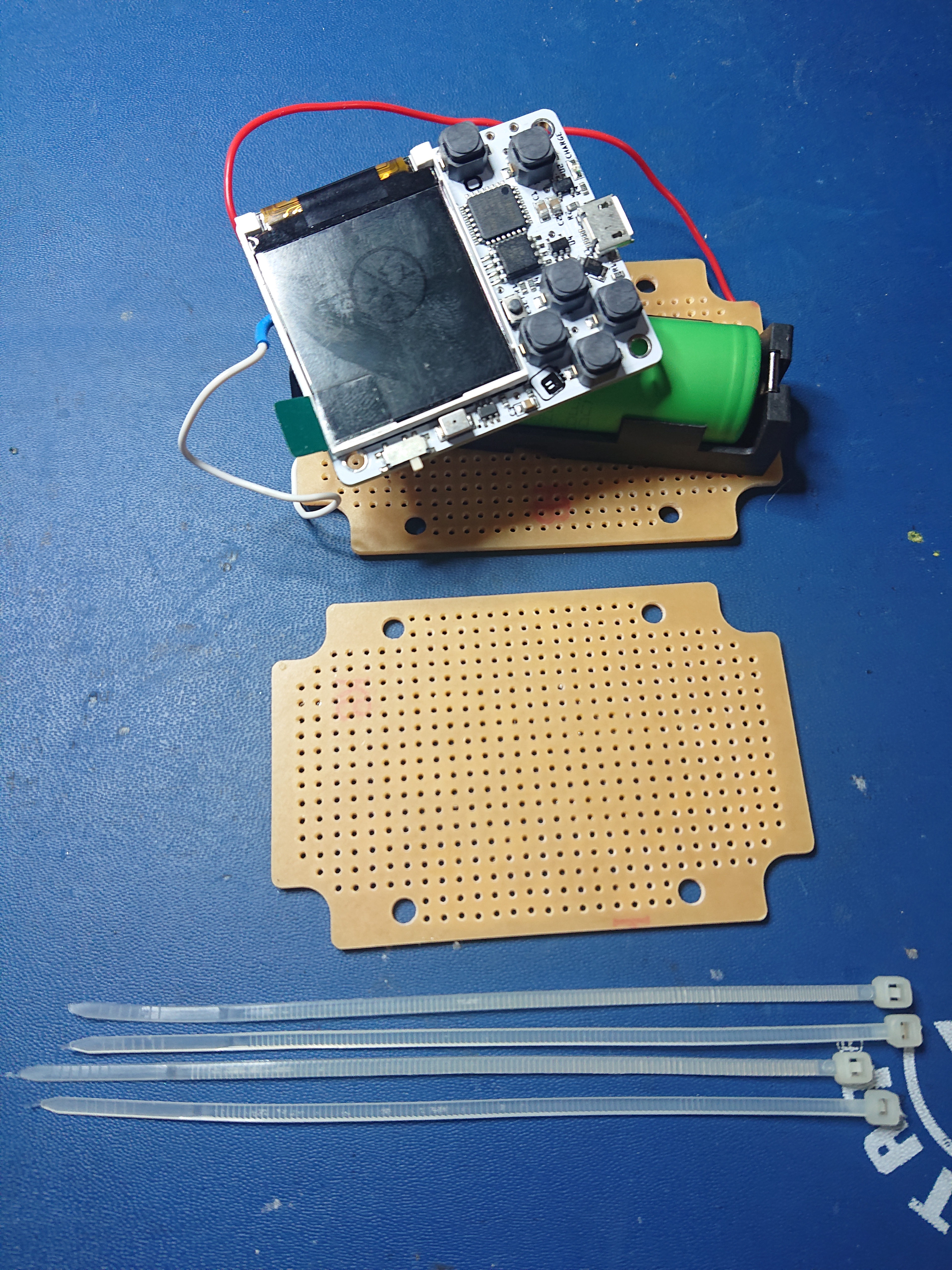
I know, the arrangement is far from perfect, and I need more training before I can attend Stackenblocken.
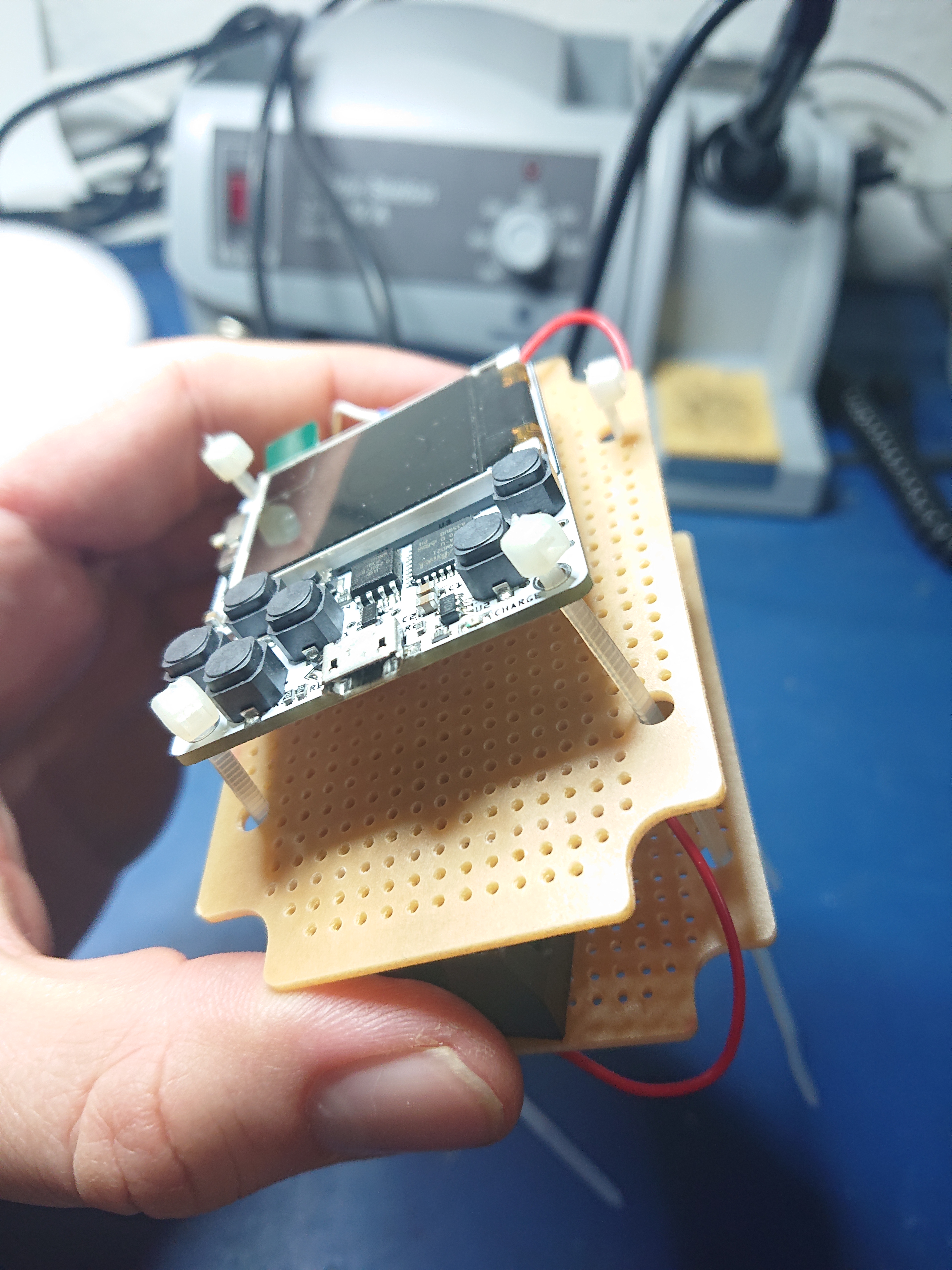
Now comes the fiddly part: Put all cable ties through the holes that you need to connect. Try to attach as many mounting holes of the uGame to the two boards as you can, and connect both boards with all cable ties to make sure the case stays small and compact and the battery is properly secured within. I recommend you put the ugame on the side of the second board which is not fit with solder points. Even though it is not likely to form a short circuit if you have boards with individual solder joints, you are on the safe side if there is no metal on the board under the uGame’s back side at all.
Now, carefully close the cable ties, going in small steps of few centimeters on each of them in round robin so that you get a somewhat straightly aligned case. You may need multiple cable ties to attach them in the correct fashion.
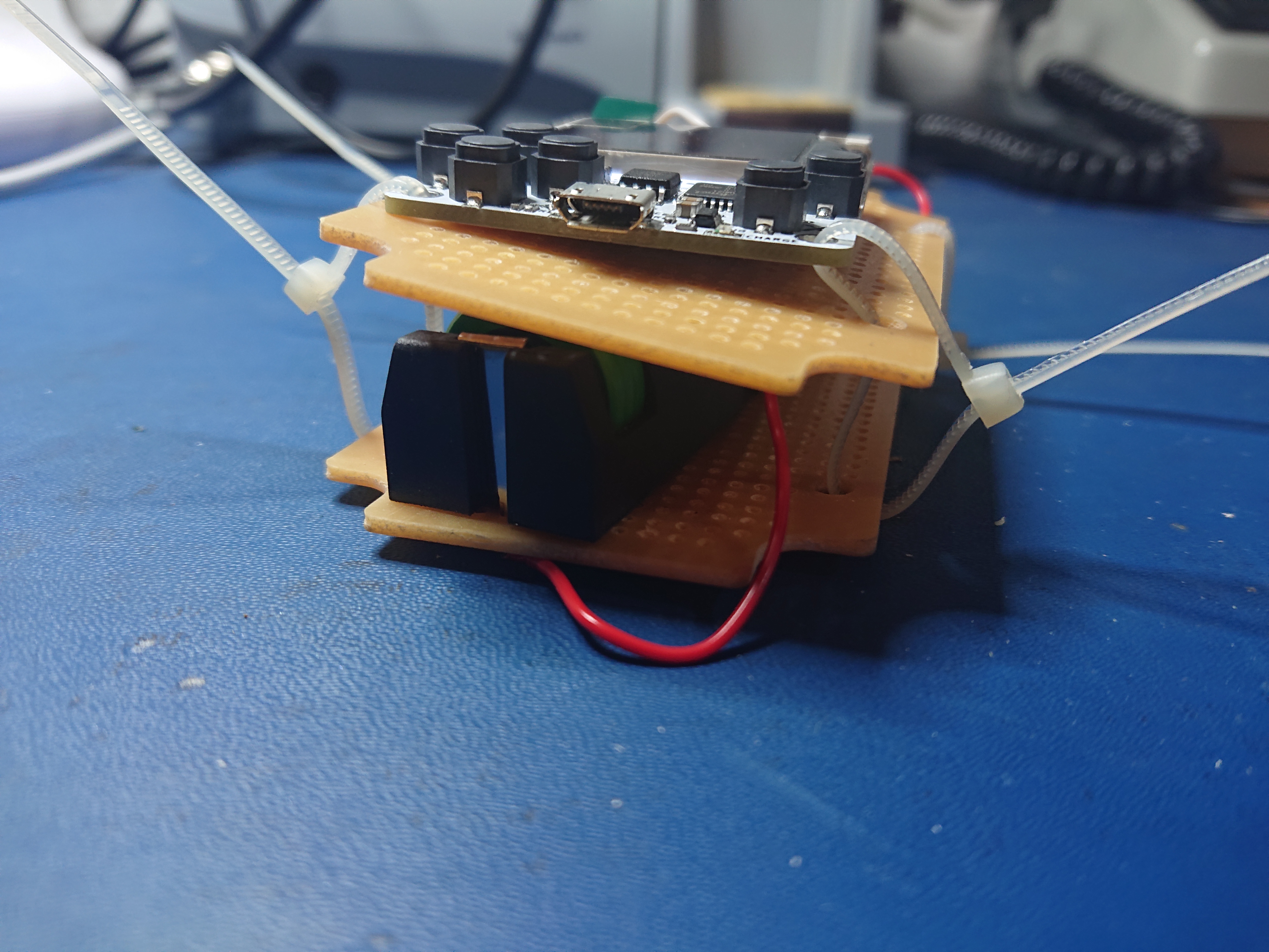
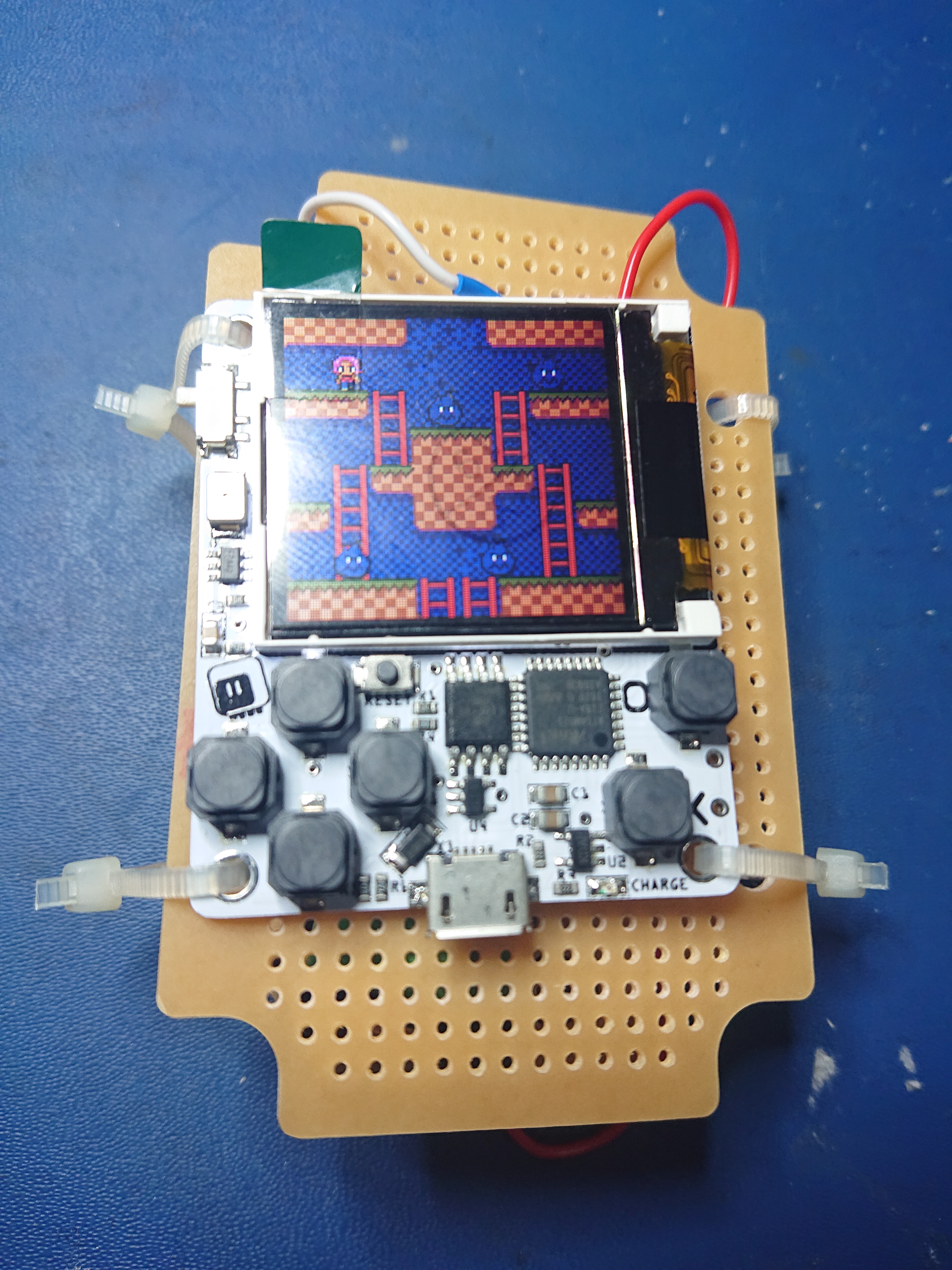
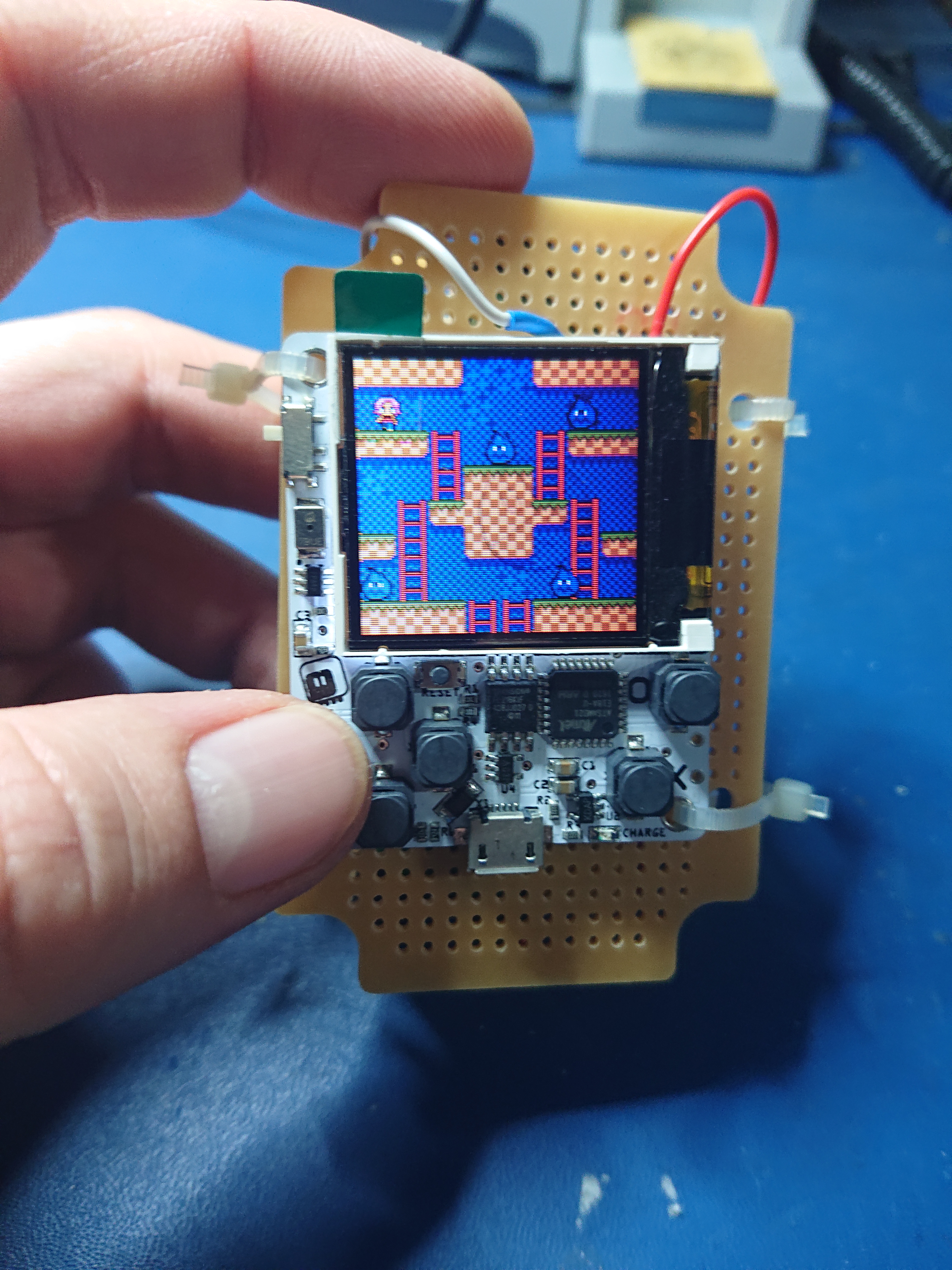
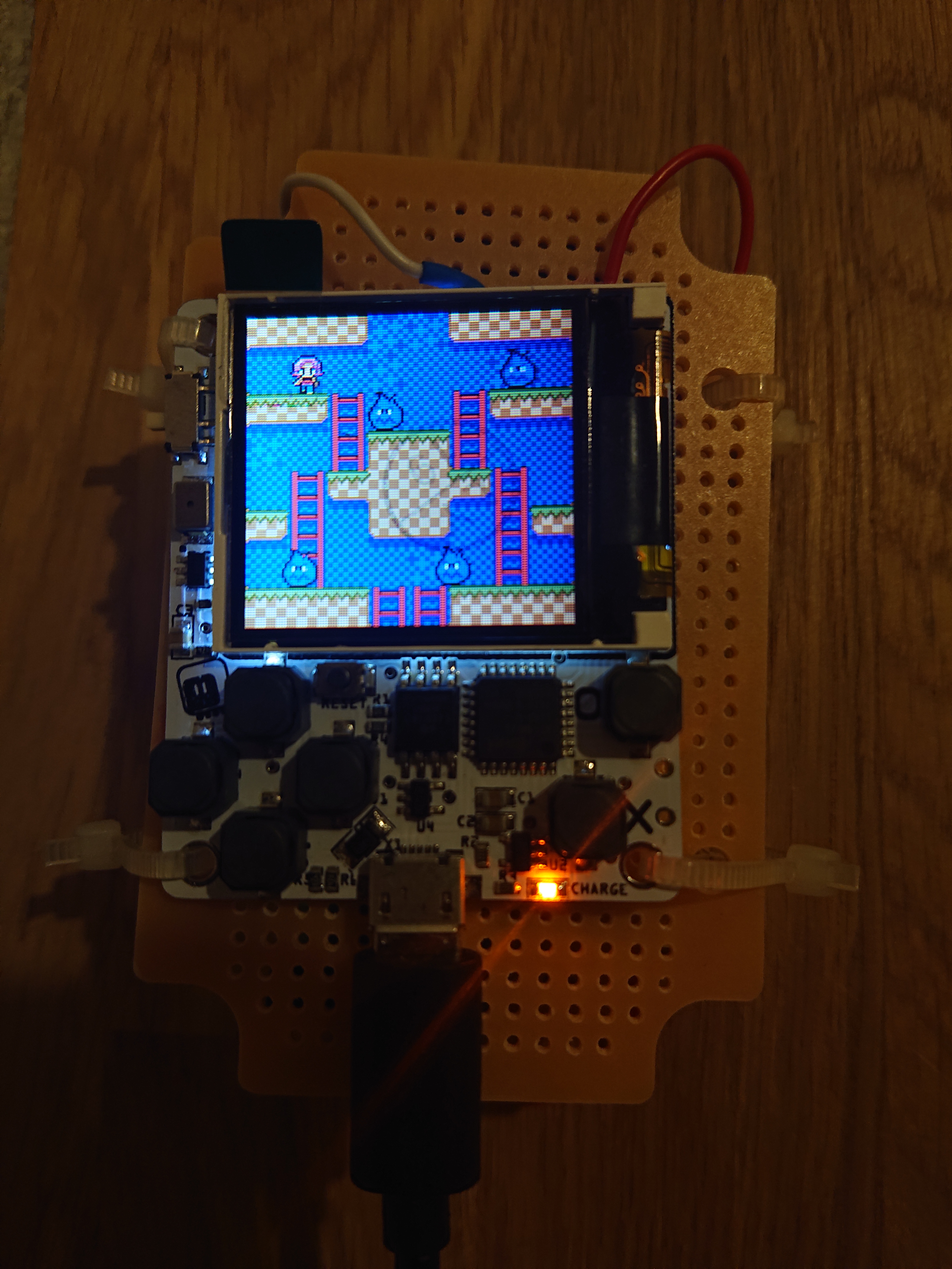
Now, when you connect the finished sandwich to the computer again, it should start charging the battery and light the CHARGE indicator LED.
I hope this blog post was somewhat useful to you. If you have any questions or remarks feel free to send me a message (see About).
Thanks for reading!
P.S.: I read just now, shortly before uploading, that uGame has been discontinued in favour of a new board by Adafruit called PyBadge (see The Last uGame). If all of this sounded very tinkery to you and scared you off the very interesting field of Python on the microcontroller, you may want to try out the Adafruit board instead which is certainly more mature. Personally, I have no intention of buying one, as I am quite content with my uGame (I hope you could tell :) ).